
- All
- Product Name
- Product Keyword
- Product Model
- Product Summary
- Product Description
- Multi Field Search

Views: 0 Author: Site Editor Publish Time: 2026-05-20 Origin: Site


Designing flexible, low-voltage heating products requires balancing thermal uniformity, mechanical flexibility, and material budgets. Many engineering failures stem from choosing the wrong substrate. You might face localized hot spots, premature material degradation, or system failure during repeated bending. We want to cut through generic marketing claims. This guide provides an engineering-focused framework for evaluating potential substrates. We ground our discussion in material science realities. You will understand the precise temperature limitations of polyethylene. You will also learn the exact operational thresholds where carbon black integration outperforms traditional etched foils or metal heating wires. By mastering these parameters, you avoid costly redesigns. You gain the insights needed to match specific thermal outputs to your project requirements. Ultimately, this approach ensures reliable, long-lasting performance for modern thermal wearables and industrial heating components.
Match Substrate to Temperature: PE carbon film is engineered strictly for low-to-medium temperature applications (typically under 90°C); it is not a substitute for high-temp polyimide (PI).
The 3-Pillar Evaluation: Successful selection requires aligning electrical (surface resistance), thermal (watt density limits), and mechanical (bend cycles) specifications.
Installation Dictates Lifespan: Even premium flexible heating film will fail if poor lamination traps air bubbles, which act as thermal insulators and create burn-inducing hot spots.
Buffer for Real-World Loss: Always calculate target power with a 20% baseline redundancy to account for conductive, convective, and radiant heat losses.
Engineering thermal wearables or low-voltage defoggers requires rigorous substrate evaluation. You must compare PE conductive carbon film against metal heating wires and other film substrates. This comparison defines its exact operational envelope. Understanding these boundaries prevents premature product failure in the field.
Metal wire heaters generate intense, localized linear heat. This uneven energy distribution causes micro-hotspots across the product surface. Conversely, a carbon black conductive film relies on the Joule heating principle. It disperses electrical energy continuously across a flat surface. This mechanism eliminates uneven thermal gradients entirely. Users feel a gentle, uniform warmth rather than sharp lines of heat.
Choosing the right base material dictates product viability. Let us break down the primary options:
Polyimide (PI/Kapton): This material withstands extreme temperatures up to 260°C. However, it remains over-engineered and cost-prohibitive for standard consumer wearables or basic defoggers.
Silicone Rubber: This material feels much thicker and heavier. It suits rugged industrial environments perfectly. Yet, it performs poorly in ultra-thin product profiles.
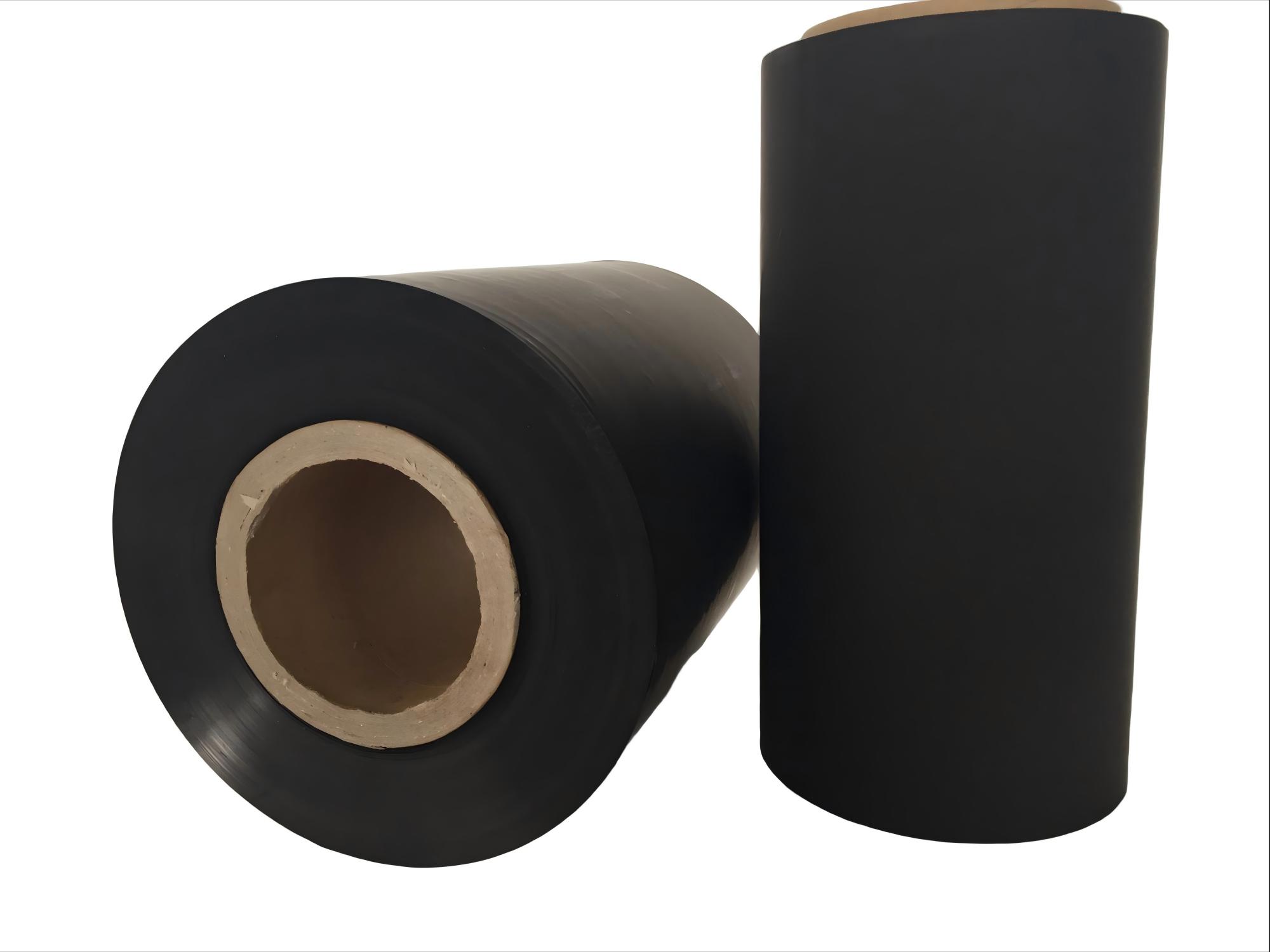
Polyethylene (PE): This remains the optimal choice for a low temperature heating film. It offers extreme thinness and high cost-efficiency. You must limit its use strictly to environments remaining below its melting threshold. Operating temperatures typically cap around 90°C to 100°C.
Substrate Material Comparison | |||
Material Type | Max Operating Temp | Profile Thickness | Best Application Scenario |
|---|---|---|---|
Polyimide (PI/Kapton) | Up to 260°C | Ultra-thin | Aerospace, Medical Devices |
Silicone Rubber | Up to 235°C | Thick & Rugged | Industrial Pipes, Drum Heaters |
Polyethylene (PE) | Up to 90°C | Ultra-thin | Wearables, Mirror Defoggers |
Flexibility defines wearable applications. These films easily endure thousands of bending cycles. They actively resist the fatigue-induced micro-fractures common in etched foil circuits. Metal foils crack under repeated stress. Carbon matrices shift and adapt safely without losing structural integrity.
Successful procurement requires a systematic evaluation model. You must align electrical, thermal, and mechanical parameters seamlessly.
First, assess surface resistance parameters. Standard ranges span from 3 Ω/sq to 10⁴ Ω/sq. This metric dictates how easily electrical current flows across the surface. Manufacturers must ensure perfectly even carbon dispersion during production. Uneven dispersion creates unpredictable resistance paths. This flaw leads inevitably to erratic thermal output and localized overheating.
Next, define the maximum safe watt density for your substrate. Over-specifying power limits risks immediate delamination. Extreme power can even melt the base material completely. Flat-plane carbon emission transfers heat highly efficiently. It outperforms round heating wires significantly. Flat surfaces allow lower overall operating temperatures. You still achieve the exact same perceived warmth. This efficiency protects the substrate from thermal degradation.
Finally, evaluate tensile strength and bend radius limits. Wearable applications demand extreme resilience. The material must withstand more than 10,000 flex cycles without suffering resistance drift. Consider die-cut versatility as well. Structural integrity matters immensely when adding connector crimps or integrated silver busbars. Ensure the PE carbon film meets these rigorous physical demands.
Transition your focus from material specifications to system design. Never rely on generic wattage charts. Every application demands custom mathematical modeling.
System designers must calculate required energy precisely. Guesswork leads to underperforming products or severe safety hazards. You must evaluate the target mass, ambient temperature, and heating duration.
Use a specific equation for accurate results. Target Power equals Warm-up Power plus Steady-State Heat. Warm-up Power represents the energy needed to raise your mass to the target temperature within a designated timeframe. Steady-State Heat represents the ongoing energy required to maintain this temperature against continuous ambient loss.
Power Calculation Variables Summary | ||
Variable Name | Description | Impact on Design |
|---|---|---|
Target Mass | Physical weight of the object receiving heat. | Higher mass requires significantly more Warm-up Power. |
Delta T (ΔT) | Difference between ambient and target temperatures. | Larger gaps increase both Warm-up and Steady-State needs. |
Timeframe | Desired duration to reach the target temperature. | Faster heating demands higher initial wattage inputs. |
Always add a minimum 20% wattage buffer. Thermal losses happen unpredictably in real-world scenarios. Conduction pulls heat directly into mounting surfaces. Convection loses thermal energy to surrounding airflow. Radiation scatters energy outward. A 20% redundancy secures stable, reliable performance across diverse environments.
Ensure your film's resistance profile aligns safely with the intended power supply. Standard systems vary widely. You might use 5V USB setups for lightweight wearables. You might deploy 7.4V battery packs for outdoor gear. Automotive defogging systems rely on 12V or 24V inputs. Aligning these voltages properly prevents catastrophic system overloads.
Material specifications only tell half the story. The physical integration process determines long-term product viability.
Many users blame material defects for product failures. However, installation error causes the most common failure modes. Even a premium flexible heating film fails quickly under poor lamination conditions.
Understand the underlying physics of lamination failure. Air bubbles act as highly effective thermal insulators. When you apply the film over gaps, trapped air prevents heat dissipation into the target surface. This blockage triggers localized thermal buildup. Hot spots form rapidly. They quickly exceed the substrate's thermal limits. This sequence causes severe material burn-through.
We recommend specific integration methods to guarantee safety.
Clean the target surface thoroughly to remove all oils and debris.
Align the film carefully before exposing the entire adhesive backing.
Use professional foam rollers to press the film down.
Roll firmly from the center outward to push trapped air out.
Apply Pressure-Sensitive Adhesive (PSA) backings cleanly.
Avoid edge-peeling, as lifting compromises the thermal bond entirely.
Always pair the film with adequate control algorithms. Integrate NTC thermistors into your circuit design. Alternatively, utilize materials exhibiting built-in PTC (Positive Temperature Coefficient) effects. These specific safeguards prevent thermal runaway. They protect both your hardware and your end users.
Selecting the right manufacturing partner mitigates severe downstream risks. You must evaluate suppliers strictly on their technical capabilities and quality control measures.
You must audit potential suppliers carefully. Look for proven batch-to-batch consistency. The conductive ink and carbon matrix dispersion must remain uniform across all production runs. Request detailed quality control reports. Inconsistent printing creates unpredictable resistance zones.
Ensure the polyethylene conductive film passes fundamental safety and environmental gates. Check for RoHS and REACH compliance documentation. Look for UL certification frameworks where applicable. Halogen-free and flame-retardant properties remain critical differentiators in global markets.
Determine if the vendor can modify the carbon loading accurately. They should hit your specific Ohm/square targets without compromising film integrity. Ask if they offer integrated silver traces. These traces ensure uniform current distribution across unusually large surface areas. True customization separates premium suppliers from generic mass-producers.
Choosing the correct material demands acknowledging absolute temperature ceilings while maximizing unique benefits. You leverage unmatched flexibility, significant cost-efficiency, and superior surface-heating uniformity. Avoid high-temperature applications where polyimide belongs. Focus entirely on optimizing low-voltage, low-temperature use cases.
We recommend starting your next phase with small-batch prototyping. Test die-cut samples under real-world flex conditions immediately. Verify your thermal distribution models using professional IR cameras. Execute these validation steps thoroughly before committing to any high-volume manufacturing run.
A: The maximum operating limit typically reaches 90°C for standard PE and PET variants. Exceeding this threshold risks severe substrate deformation and melting. For applications demanding temperatures above 150°C, you must pivot to high-temperature polyimide (PI) or Kapton materials.
A: Carbon fiber relies on a woven mesh of individual filaments. This mesh can break under severe folding. Conversely, carbon film uses a homogeneous conductive matrix printed directly onto the substrate. This offers a much thinner profile and highly uniform surface heat, though it possesses lower puncture resistance.
A: Yes, but cutting alters the overall resistance path significantly. Custom shapes require careful pre-calculation. You must plan busbar placement and current flow patterns accurately before cutting. This pre-planning helps you avoid creating unheated dead zones or dangerous hot spots.
